
Three-phase electrical calculations form the backbone of modern power distribution systems, from industrial facilities to renewable energy installations. Understanding these calculations isn’t just about following formulas – it’s about ensuring safety, efficiency, and optimal performance in complex electrical systems.
Master three-phase power calculations to:
– Accurately size conductors and protection devices
– Determine proper load distribution
– Calculate voltage drops and power losses
– Ensure system stability and reliability
Whether you’re designing a new industrial installation or upgrading an existing power system, precise three-phase calculations are crucial. They help prevent equipment damage, reduce energy waste, and maintain consistent power delivery across all phases. This article breaks down essential three-phase calculations into practical, step-by-step methods that both experienced engineers and technical professionals can immediately apply.
We’ll explore fundamental concepts like apparent power, true power, and power factor, then progress to advanced calculations for balanced and unbalanced loads. Each section includes worked examples and real-world applications to reinforce your understanding and build practical expertise in three-phase power system design and analysis.
Understanding Three-Phase Power Fundamentals
Three-Phase Voltage and Current Relationships
In three-phase systems, understanding the relationship between line and phase values is crucial for accurate calculations. The line-to-line voltage (VL-L) is the voltage measured between any two phases, while the line-to-neutral voltage (VL-N) is measured between any phase and the neutral point.
For a balanced wye (star) configuration:
VL-L = VL-N × √3
IL-L = IL-N
In delta configurations:
VL-L = VPhase
IL-L = IPhase × √3
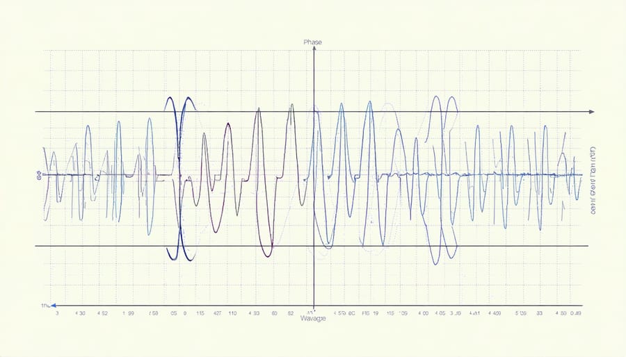
The three phases in a balanced system are separated by 120° electrical degrees, creating a symmetrical power distribution. This phase relationship ensures consistent power delivery and is fundamental to the efficiency of three-phase systems.
Current calculations must consider the system configuration:
– In wye systems, line current equals phase current
– In delta systems, line current is √3 times the phase current
Power factor also impacts these relationships, as it affects the phase angle between voltage and current waveforms. For accurate calculations, always verify whether you’re working with line or phase values and confirm the system configuration (delta or wye) before applying these relationships.
Power Factor in Three-Phase Systems
Power factor plays a crucial role in three-phase battery systems, directly affecting system efficiency and component sizing. In ideal conditions, voltage and current waveforms are perfectly aligned, resulting in a power factor of 1.0. However, real-world applications often experience power factors between 0.8 and 0.95 due to inductive or capacitive loads.
To calculate the actual power consumption in a three-phase system, multiply the apparent power by the power factor:
Real Power (P) = √3 × VL × IL × PF
Where:
– VL = Line voltage
– IL = Line current
– PF = Power factor
A lower power factor means more current is needed to deliver the same amount of real power, resulting in higher transmission losses and larger conductor requirements. For battery systems, this translates to increased battery capacity needs and potentially higher installation costs.
To optimize system efficiency, consider implementing power factor correction using capacitor banks, especially when dealing with large inductive loads like motors. This helps maintain system stability and reduces unnecessary strain on batteries and inverters.
Essential Three-Phase Power Calculations
Real Power Calculations
In three-phase systems, calculating real (active) power requires careful consideration of both voltage and current relationships. The fundamental formula for three-phase real power is P = √3 × VL × IL × PF, where VL represents line voltage, IL is line current, and PF is the power factor.
For balanced loads, the calculation can be simplified using either line-to-line or line-to-neutral measurements. When using line-to-neutral values, multiply the result by 3 to account for all phases. For example, a system with 400V line-to-line voltage, 100A line current, and 0.85 power factor would yield: P = √3 × 400V × 100A × 0.85 = 58,990 watts.
To convert watts to watt-hours, multiply the power by the time in hours. This is particularly important when calculating energy consumption over specific periods.
For unbalanced loads, measure each phase separately and sum the results:
P = (V1 × I1 × PF1) + (V2 × I2 × PF2) + (V3 × I3 × PF3)
Remember that true power measurements should always account for power factor, as apparent power (VA) calculations alone may not reflect actual energy consumption. For precise measurements, using a three-phase power analyzer is recommended, especially in systems with significant harmonic content or varying loads.
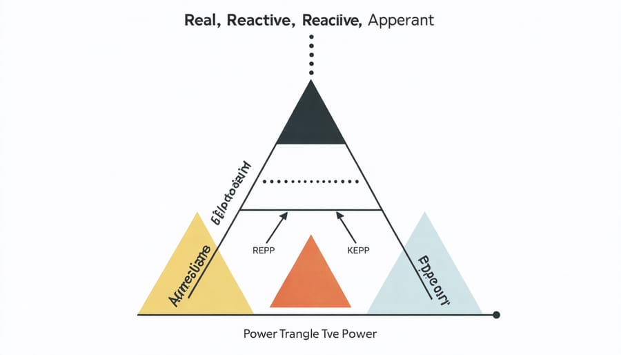
Apparent and Reactive Power
In three-phase systems, apparent power (measured in VA) and reactive power (measured in VAR) play crucial roles in determining system capacity and efficiency. Apparent power represents the total power delivered to a load, combining both real power (watts) and reactive power, while reactive power represents the portion of power that oscillates between the source and load without performing useful work.
To calculate apparent power in a balanced three-phase system:
S = √3 × VL × IL
Where:
S = Apparent power in VA
VL = Line-to-line voltage
IL = Line current
For reactive power calculation:
Q = √(S² – P²)
Where:
Q = Reactive power in VAR
S = Apparent power in VA
P = Real power in watts
Understanding these values is essential for proper system sizing and power factor correction. For example, when specifying a three-phase inverter for a solar installation, you must ensure its VA rating exceeds the maximum apparent power demand of your loads. Similarly, reactive power compensation equipment selection depends on accurate VAR calculations.
Power factor, which is the ratio of real power to apparent power (P/S), indicates how effectively electrical power is being used. A higher power factor (closer to 1.0) indicates more efficient power utilization and often results in reduced operating costs.
Battery Capacity Requirements
Determining battery capacity requirements for three-phase systems requires careful consideration of both total power demand and system voltage. To calculate the necessary battery capacity, first determine the total power requirement in watts (W) by multiplying the voltage (V) by the current (A) and the square root of 3 (approximately 1.732) for balanced three-phase loads.
For a typical three-phase system, you’ll need to account for peak load demands, backup duration requirements, and system efficiency losses. To convert amp-hours to kilowatt-hours, multiply the amp-hour rating by the system voltage and divide by 1000.
When sizing battery banks, consider the depth of discharge (DoD) to preserve battery life. Most deep-cycle batteries shouldn’t be discharged below 50% capacity. Therefore, the calculated capacity should be doubled to maintain this safety margin.
For example, if your three-phase system requires 15kW of power for 4 hours of backup time, you’ll need:
15kW × 4 hours = 60kWh total energy storage
Accounting for 50% DoD: 60kWh × 2 = 120kWh actual battery capacity required
Remember to factor in temperature effects, as battery capacity typically decreases in cold conditions. Add 10-20% capacity for temperatures below 20°C (68°F) to ensure reliable system performance.
Practical Application Examples
UPS System Sizing
Let’s walk through a practical example of sizing a three-phase UPS system for a critical load facility. The process involves several key calculations to ensure proper system capacity and reliability.
First, determine the total connected load power:
– Calculate the sum of all critical loads in kVA
– Include future expansion (typically 20-30%)
– Account for power factor correction
Example calculation:
Connected Load = 100 kW
Power Factor = 0.8
Required kVA = 100 kW ÷ 0.8 = 125 kVA
Next, consider the runtime requirements and perform battery capacity calculations for the desired backup duration:
– Determine required backup time (minutes)
– Calculate total energy needed (kWh)
– Factor in battery efficiency (typically 85-90%)
For our example:
Required Runtime = 30 minutes
Energy Required = 125 kVA × 0.5 hours = 62.5 kVAh
With 85% efficiency: 62.5 ÷ 0.85 = 73.5 kVAh
Finally, include safety factors:
– Temperature derating (1.1)
– Aging factor (1.25)
– System redundancy requirements (N+1 or 2N)
Final UPS Rating = Base kVA × Temperature Factor × Aging Factor
125 kVA × 1.1 × 1.25 = 171.875 kVA
Choose the next standard UPS size available (typically 200 kVA in this case) to ensure adequate capacity and future scalability. Remember to verify that the selected UPS system can handle the inrush current of the connected loads and maintain proper voltage regulation within specified limits.
Industrial Battery Bank Design
When designing an industrial battery bank for three-phase systems, several critical calculations must be considered to ensure optimal performance and reliability. The first step involves determining the total power requirements in kilowatt-hours (kWh) based on the connected load and desired backup duration.
To size the battery bank correctly, you’ll need to perform a watt-hours to amp-hours conversion while accounting for the system voltage and efficiency losses. For three-phase applications, the calculation must consider the balanced load distribution across all phases.
The basic formula for determining battery capacity is:
Required Capacity (Ah) = (Total Power × Backup Hours × Safety Factor) ÷ (System Voltage × DOD × Efficiency)
Where:
– Total Power is the sum of all phase loads in watts
– Safety Factor typically ranges from 1.1 to 1.25
– DOD (Depth of Discharge) is usually 0.5 to 0.8
– System Efficiency typically ranges from 0.85 to 0.95
For industrial applications, it’s essential to consider:
1. Temperature compensation factors
2. Future load expansion requirements
3. Battery configuration (series/parallel arrangement)
4. Charging system capacity
5. Maintenance requirements
The battery bank must be configured to match the inverter’s DC input requirements while maintaining proper voltage levels. For example, a 480V three-phase system might require 40 batteries in series (12V each) to achieve the necessary DC bus voltage.
Remember to factor in surge requirements for motor starts and other high-inrush loads common in industrial settings. The battery bank should be capable of handling these momentary demands without excessive voltage drop.

Load Balancing Calculations
Load balancing in three-phase systems is crucial for maintaining system efficiency and preventing equipment damage. Each phase should carry approximately equal loads to ensure optimal performance and minimize neutral current. The goal is to achieve a load imbalance of less than 20% between phases.
To calculate load balance, first measure the current in each phase:
1. Calculate the average current:
Iavg = (I1 + I2 + I3) ÷ 3
where I1, I2, and I3 are individual phase currents
2. Determine the percentage imbalance:
% Imbalance = [(Imax – Iavg) ÷ Iavg] × 100
where Imax is the highest phase current
For voltage imbalance calculations:
% Vimbalance = [(Vmax – Vavg) ÷ Vavg] × 100
where Vmax is the highest phase-to-phase voltage
and Vavg is the average of all phase-to-phase voltages
When distributing new loads:
– Maintain similar power requirements across phases
– Consider both current magnitude and power factor
– Account for existing loads on each phase
– Document load distribution for future reference
Regular monitoring and adjustment of load distribution helps maintain system efficiency and extends equipment life. For optimal performance, aim to keep imbalance below 5% in most applications.
Three-phase electrical calculations are fundamental to ensuring safe, efficient, and reliable power systems. Throughout this guide, we’ve explored the essential components and formulas needed to master these calculations, from basic power equations to complex load balancing considerations.
Remember that accurate three-phase calculations are crucial for proper system sizing, equipment selection, and maintenance planning. The relationship between voltage, current, and power in three-phase systems provides advantages over single-phase setups, including more efficient power transmission and better performance for large industrial equipment.
Key takeaways from our discussion include:
– The importance of understanding both line-to-line and line-to-neutral measurements
– How to calculate three-phase power using both the simple and detailed methods
– The critical role of power factor in system efficiency
– Methods for determining proper conductor sizing and voltage drop
– Techniques for load balancing across all three phases
In practical applications, these calculations are essential for:
– Designing new electrical installations
– Upgrading existing systems
– Troubleshooting power quality issues
– Optimizing energy efficiency
– Ensuring compliance with electrical codes
When working with three-phase systems, always double-check your calculations and consider safety margins in your final designs. It’s recommended to use appropriate calculation tools and software while maintaining a solid understanding of the underlying principles. Regular system monitoring and maintenance, guided by these calculations, will help ensure optimal performance and longevity of your electrical installation.
For complex installations or critical applications, consider consulting with qualified electrical engineers to verify calculations and ensure all safety and regulatory requirements are met. Keep detailed records of all calculations and measurements for future reference and system maintenance.