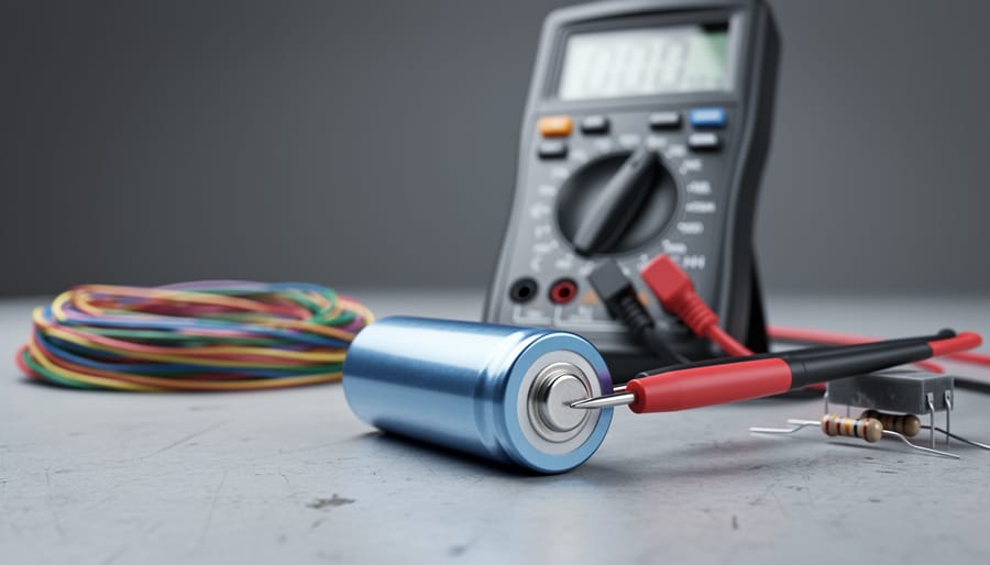
Calculating the electromotive force (EMF) of a battery requires a digital multimeter and a basic understanding of Ohm’s Law. The most accurate method involves measuring the open-circuit voltage with no load connected, which gives you the battery’s EMF directly. For a more complete picture, you’ll also measure terminal voltage under load and use the formula: EMF = V + Ir, where V is the terminal voltage, I is the current, and r is the internal resistance.
This calculation matters because EMF represents the maximum potential difference a battery can provide, while terminal voltage tells you what’s actually available to your circuit. The difference between these values reveals internal resistance, a critical parameter for sizing battery systems in solar installations, portable electronics, and backup power applications.
Battery EMF calculation becomes essential when designing power systems that demand precise voltage regulation or when diagnosing underperforming batteries in the field. Engineers and technicians working with lithium-ion, lead-acid, or alkaline cells need to understand both theoretical EMF and practical terminal voltage to prevent system failures and optimize energy delivery.
The process takes about 5-10 minutes per battery and requires minimal equipment: a quality multimeter, a known load resistor, and basic safety gear. Understanding the relationship between EMF, internal resistance, and load current helps you predict battery performance across varying discharge rates and temperature conditions, skills that separate competent technicians from those who simply swap components without diagnosis.
Understanding EMF vs Terminal Voltage
When you connect a multimeter to a battery sitting on your workbench, you’re measuring terminal voltage, not the battery’s true electromotive force (EMF). These two values differ because of what happens inside the battery itself.
EMF represents the maximum potential difference a battery can provide when no current flows through it. It’s the theoretical voltage generated by the chemical reactions inside the battery under ideal conditions. Terminal voltage, on the other hand, is the actual voltage you measure at the battery’s terminals when current flows to power a load. The terminal voltage is always lower than the EMF when the battery is delivering power.
The difference between these two values comes down to internal resistance. Every battery contains materials that resist the flow of electrons, the electrolyte, separator membranes, and electrode materials all contribute some resistance. When current flows through the battery, this internal resistance causes a voltage drop inside the battery itself, reducing the voltage available at the terminals.
Think of it like water pressure in a pipe with a partially clogged section. The pump (EMF) generates a certain pressure, but friction in the clog (internal resistance) reduces the pressure you measure downstream (terminal voltage). The harder the water flows (more current), the bigger the pressure drop.
This relationship between terminal voltage vs EMF follows a simple equation: Terminal Voltage = EMF – (Internal Resistance × Current). As current increases, the voltage drop across the internal resistance grows, and terminal voltage decreases further. This explains why your battery-powered drill slows down as the battery drains, not only does the EMF decrease slightly, but the internal resistance typically increases, reducing terminal voltage even more under the same load.
Tools and Materials Required
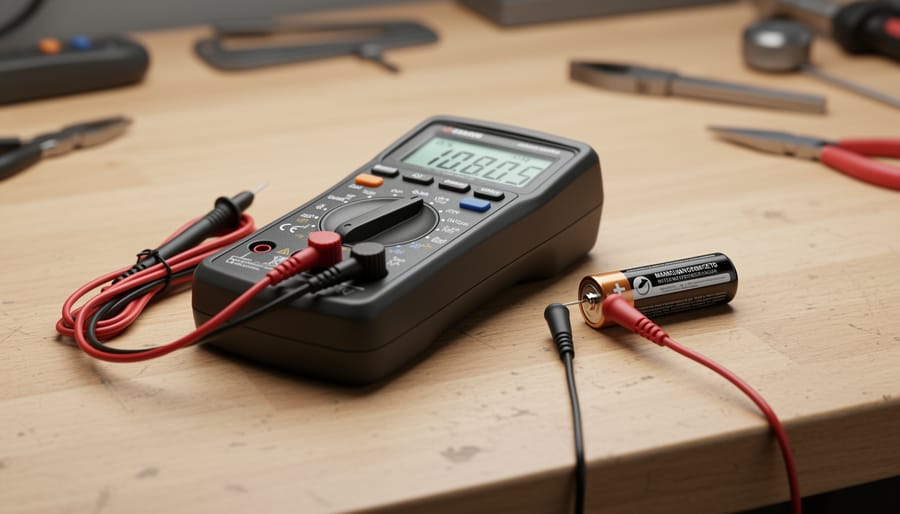
To accurately measure and calculate battery EMF, you’ll need several tools that most electronics professionals already have in their workspace. The measurements require precision, so investing in quality equipment pays off when you need reliable data for battery assessment or solar system design.
Here’s what you’ll need:
- Digital multimeter with at least 0.01V resolution and accuracy within ±0.5% for precise voltage measurements
- Load resistor matched to your battery capacity (typically 10-100 ohms for small batteries, 1-10 ohms for larger batteries like those in solar installations)
- Calculator or spreadsheet software for performing the EMF calculations and tracking multiple measurement sets
- Stopwatch or timer to ensure consistent measurement intervals and proper battery rest periods
- Battery terminal cleaning brush to remove corrosion that could affect voltage readings
- Insulated test leads with alligator clips for secure, safe connections during testing
- Optional: Data logger or multimeter with logging capability to track voltage changes over time
- Optional: Clamp ammeter for measuring current in high-capacity battery systems without breaking the circuit
The digital multimeter is your primary tool, and it’s worth using one with true RMS capability if you’re working with batteries that may have ripple voltage from charging systems. For the load resistor, choose a power rating at least double the expected power dissipation (calculated as I²R) to prevent overheating during measurements. If you’re working with battery banks in solar installations, a higher wattage resistor or resistor bank becomes necessary to handle the larger currents these systems produce.
Safety Precautions
Working with batteries requires respect for their stored energy and chemical composition. Even a small battery can deliver dangerous current if mishandled, and larger batteries used in solar installations present serious hazards.
Before starting any EMF measurements, ensure your workspace has adequate ventilation, especially when working with lead-acid batteries that can emit hydrogen gas during charging or if overheated. Work outdoors or in a well-ventilated area whenever possible. Wear safety glasses to protect your eyes from potential acid splashes or sparks, and consider chemical-resistant gloves when handling lead-acid or nickel-cadmium batteries.
Different battery chemistries demand specific precautions. Lead-acid batteries contain sulfuric acid that can cause severe chemical burns and produce flammable hydrogen gas. Lithium-ion batteries, common in modern solar setups, can enter thermal runaway if damaged or short-circuited, leading to intense fires that are difficult to extinguish. Handle swollen or damaged lithium batteries with extreme caution and dispose of them properly rather than testing them.
When connecting load resistors for EMF measurements, double-check your circuit before applying power. Use resistors rated for adequate wattage to prevent overheating. For high-capacity batteries in solar installations (typically 100Ah or larger), use a load resistor that limits current to safe levels, usually 1-5 amps for testing purposes. Keep flammable materials away from your work area, and have a Class D fire extinguisher nearby when working with lithium batteries.
Always disconnect the positive terminal first when removing batteries from service and connect it last during installation to minimize short-circuit risk.
Step-by-Step EMF Calculation Process
Step 1: Measure Open-Circuit Voltage
The open-circuit voltage represents your battery’s voltage when no current flows through it. This baseline measurement is crucial for accurate EMF calculations.
Before connecting your multimeter, ensure the battery has been disconnected from all loads for at least 30 minutes. For batteries recently under heavy load or charging, wait 2-4 hours to allow internal chemical processes to stabilize. Lithium-ion batteries stabilize faster than lead-acid types.
Set your digital multimeter to DC voltage mode with a range appropriate for your battery, typically 20V for 12V systems. Connect the red probe to the positive terminal and the black probe to the negative terminal. Ensure firm contact without forcing connections that could damage terminals.
Record the displayed voltage to two decimal places (e.g., 12.84V). Take three readings spaced one minute apart and average them to account for minor fluctuations. This open-circuit voltage will serve as your reference point when comparing against loaded voltage measurements in the next step. Temperature significantly affects readings, so note the ambient temperature alongside your measurement for later reference.
Step 2: Measure Voltage Under Load
Once you’ve recorded your open-circuit voltage, it’s time to measure how the battery performs under actual working conditions. This step reveals the voltage drop caused by internal resistance, which is crucial for determining true EMF.
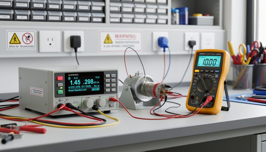
Start by connecting your load resistor across the battery terminals. Use alligator clips or a secure connection method to ensure stable contact. For most household batteries, a 10-50 ohm resistor works well. Higher capacity batteries like those in solar systems may require lower resistance values (1-10 ohms) to draw sufficient current for meaningful measurements.
With the load connected, immediately measure the terminal voltage using your digital multimeter. This voltage will be lower than your open-circuit reading because current is now flowing through the battery’s internal resistance. Record this value, label it as V_load in your notes.
Now calculate the current flowing through your load resistor using Ohm’s law: I = V/R. Divide your loaded terminal voltage by the resistance value of your load resistor. For example, if you measured 11.8V across a 10-ohm resistor, the current is 11.8V ÷ 10Ω = 1.18A. If your multimeter displays smaller values in milliamps, you can convert mA to amps by dividing by 1000.
Keep the load connected only long enough to get a stable voltage reading, typically 10-30 seconds. Prolonged connection can heat the resistor and affect accuracy, particularly with smaller load resistors drawing higher currents.
Step 3: Calculate Internal Resistance and EMF
With your no-load voltage (V₀) and loaded voltage (V_L) recorded, along with the current draw (I) you calculated in Step 2, you can now determine both the internal resistance and the true EMF of your battery.
The internal resistance (r) represents the opposition to current flow within the battery itself. Calculate it using the formula:
r = (V₀ – V_L) / I
This gives you the resistance in ohms. Once you have the internal resistance, apply the fundamental relationship where EMF equals V plus Ir to find the electromotive force.
Here’s a complete worked example using realistic values from a 12V lead-acid battery:
- Open-circuit voltage measured: V₀ = 12.8V
- Voltage under 10Ω load: V_L = 12.2V
- Current calculated (from Step 2): I = 12.2V / 10Ω = 1.22A
- Internal resistance: r = (12.8V – 12.2V) / 1.22A = 0.6V / 1.22A = 0.49Ω
- EMF calculation: EMF = V_L + (I × r) = 12.2V + (1.22A × 0.49Ω) = 12.2V + 0.60V = 12.8V
Notice the calculated EMF matches the open-circuit voltage in this example. That’s your quality check, the EMF should equal or very closely approximate your no-load reading for a healthy battery. Small discrepancies (within 0.1V) typically stem from measurement precision or brief voltage settling during your readings.
For lithium-ion batteries, you’ll see lower internal resistance values, often 0.05Ω to 0.2Ω, while older lead-acid batteries may show 0.8Ω or higher. Record both your EMF and internal resistance values, tracking internal resistance over time reveals battery degradation better than voltage readings alone.
EMF Calculation Methods Compared
Beyond the basic single-load method covered earlier, you can calculate battery EMF using several alternative approaches, each with distinct advantages depending on your situation and equipment availability.
The two-load method offers superior accuracy by eliminating measurement uncertainties. Connect two different known resistances sequentially, measuring terminal voltage and calculating current for each. Plot these two voltage-current pairs and draw a straight line between them. The y-intercept where current equals zero represents the EMF, while the line’s negative slope gives internal resistance. This approach minimizes the impact of measurement errors because you’re using two data points rather than relying on a single open-circuit reading.
The graphical V-I method extends this principle further. Measure terminal voltage across multiple load conditions, creating at least four to six data points spanning low to moderate current draws. Plot voltage on the y-axis against current on the x-axis. The resulting line’s y-intercept is your EMF. This method excels when you suspect non-linear behavior or want comprehensive battery characterization, though it requires more time and equipment.
Using manufacturer specifications provides a quick reference point without measurements. Battery datasheets list nominal EMF values for new cells. This works for preliminary calculations or when you need rough estimates for system design. However, actual EMF degrades over battery life, so specifications alone cannot tell you current battery condition.
Choose the single-load method for routine checks and field work. Select the two-load or graphical approaches when precision matters for research, quality control, or diagnosing performance issues. Reserve manufacturer specs for planning stages before physical batteries arrive.
Verification and Troubleshooting
After completing your EMF calculation, cross-check your result against the nominal voltage for that battery chemistry. Lithium-ion cells typically show 3.6-3.7V EMF per cell, lead-acid batteries measure around 2.1V per cell (12.6V for a 12V battery), and NiMH cells register approximately 1.2-1.25V. If your calculated EMF falls outside these ranges by more than 10%, recheck your measurements and math.
Compare your calculated internal resistance to typical values as a secondary verification. Fresh lithium-ion cells exhibit 50-100mΩ, lead-acid batteries range from 5-20mΩ depending on size and age, while NiMH cells show 50-200mΩ. These benchmarks help confirm your calculation accuracy and identify potential battery degradation.
Common calculation errors produce recognizable patterns:
- Readings that change rapidly indicate insufficient rest time before measuring open-circuit voltage or poor probe contact
- Calculated EMF lower than terminal voltage suggests reversed measurements or incorrect formula application
- Unrealistic internal resistance values (negative numbers or values in the thousands of ohms) point to incorrect current calculations or load resistance measurement errors
When troubleshooting inconsistent readings, verify your load resistor matches its stated value using your multimeter’s resistance mode. Temperature variations affect battery voltage by 0.3-0.5% per degree Celsius, so perform all measurements at similar temperatures. For capacity-based calculations, use our Ah to Wh conversion tool and Watts to watt-hours calculator to ensure your energy measurements align with your EMF results.
Repeat the measurement process three times and average your results. If values differ by more than 5%, inspect battery terminals for corrosion, check all connections, and allow longer rest periods between measurements.
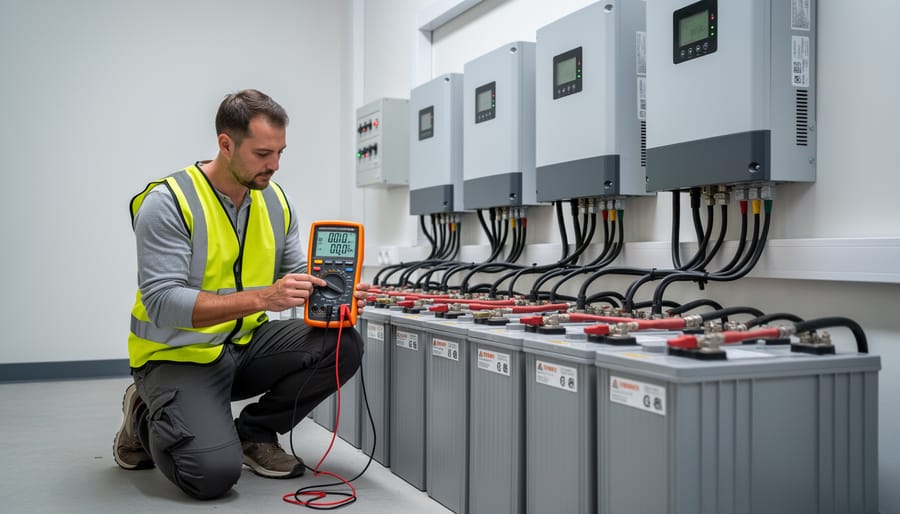
Real-World Applications in Solar Systems
Knowing how to calculate battery EMF transforms abstract measurements into practical decisions for solar installations. When sizing a battery bank for an off-grid system, accurate EMF values reveal the true usable capacity rather than relying on nameplate ratings that often overestimate performance. For example, if your 12V battery bank shows an EMF of 11.8V instead of the expected 12.6V, you’re working with roughly 15% less capacity than planned, critical information that prevents undersizing your storage.
EMF calculations excel at catching battery degradation before it causes system failures. Compare your current EMF measurement against the manufacturer’s specification (typically 12.6V for lead-acid, 13.2V for lithium). A fully charged battery showing EMF below these thresholds signals sulfation in lead-acid cells or capacity fade in lithium chemistries. Track this monthly; when EMF drops 5% from baseline, plan for replacement within six months.
Charge controller optimization depends on knowing actual EMF values, not assumed voltages. Set your bulk charging cutoff 0.2-0.3V above measured EMF to ensure complete charging without overcharging. If your lithium bank measures 13.1V EMF but your controller uses a generic 13.6V absorption setpoint, you’re unnecessarily stressing the cells. This adjustment alone can extend battery life by 20-30% in solar applications where daily cycling is standard.
Solar installers who verify EMF during commissioning catch manufacturing defects and damaged cells before warranty periods expire, saving thousands in replacement costs.
Frequently Asked Questions
Can I measure EMF with a multimeter alone?
No, a multimeter alone won’t give you the true EMF. What you measure directly is terminal voltage, which is always lower than EMF when current flows due to internal resistance. You need to take two measurements, open-circuit voltage and voltage under load, then calculate EMF using the formula EMF = V + Ir.
How does temperature affect EMF readings?
Temperature significantly impacts battery voltage, with most batteries losing about 0.5-1% of their voltage per 10°C drop below room temperature. For accurate EMF calculations, measure your battery at a stable temperature, ideally 25°C (77°F), or note the temperature and allow at least 30 minutes for thermal stabilization before taking readings.
What’s considered normal internal resistance for common batteries?
Typical internal resistance varies widely by chemistry and size: AA alkaline batteries show 0.1-0.3 ohms, 12V lead-acid car batteries range from 0.01-0.02 ohms when new, lithium-ion 18650 cells measure 0.03-0.05 ohms, and large-format lithium batteries used in solar systems often fall below 0.01 ohms. Higher values indicate aging or degradation.
How often should I calculate EMF to monitor battery health?
For solar system batteries, calculate EMF quarterly during routine maintenance checks. If you notice performance issues like reduced runtime or slower charging, measure immediately. Monthly calculations make sense for critical backup systems where battery failure would be costly.
Does battery age change the EMF value?
The theoretical EMF determined by battery chemistry remains relatively constant, but internal resistance increases with age and cycling, which affects the terminal voltage you measure under load. A battery that once showed 12.6V under load might drop to 12.2V after several years due to higher internal losses, even though the fundamental EMF stays near the same value.
Can I use EMF calculations for capacity testing?
EMF calculations primarily reveal internal resistance and voltage characteristics rather than capacity (amp-hours). For capacity assessments, you’ll need discharge testing combined with Wh to Ah conversion calculations to determine actual energy storage. EMF measurements complement capacity tests by identifying batteries with elevated internal resistance that may fail under high-current demands even if their amp-hour rating appears adequate.
These questions come up repeatedly when professionals perform battery electrical calculations in the field. Understanding these nuances helps you interpret your measurements correctly and avoid common pitfalls that lead to inaccurate EMF determinations or misdiagnosis of battery condition.
Mastering EMF calculations gives you precise insight into your battery’s true electrical potential, essential for reliable solar system design and battery health monitoring. The three-step process outlined here, measuring open-circuit voltage, testing under load, and applying the EMF formula, provides accurate results that go beyond simple voltage readings to reveal internal resistance and actual performance characteristics.
Apply this method to your own batteries regularly, especially before major solar installations or when evaluating battery degradation over time. The calculation takes only minutes but delivers critical data for sizing battery banks correctly and preventing unexpected power failures. For lithium-ion batteries in solar applications, quarterly EMF checks help catch declining performance before it impacts your system’s reliability.
Take your battery calculations further with our related tools designed for solar professionals. Our amp-hour calculator converts capacity ratings across different discharge rates, while the watt-hour calculator helps you match battery storage to actual load requirements. Both tools integrate seamlessly with the EMF values you’ve just learned to measure, giving you complete electrical specifications for confident system planning.
Start calculating your battery EMF today. The insights you gain will improve every aspect of your battery management and solar energy projects.