

Calculating total resistance in series-parallel networks requires identifying circuit sections, solving series combinations first (R₁ + R₂), then parallel sections (1/Rtotal = 1/R₁ + 1/R₂), and working systematically from the farthest branches toward the power source. This structured approach, combined with a reliable calculator, reduces errors and saves time whether you’re designing solar array bypass protection, troubleshooting electronics, or verifying student work.
Most circuits in real-world applications use mixed configurations. A solar combiner box might have multiple strings in parallel, each containing bypass diodes in series. An LED driver circuit could combine current-limiting resistors in ways that aren’t purely one topology. Getting these calculations wrong leads to overheating, inefficient power delivery, or component failure.
The challenge isn’t just arithmetic. It’s recognizing which resistors share current (series) versus which share voltage (parallel), then applying the right formula to each group in the correct sequence. A single misidentified connection changes your entire result. That’s where both method and verification matter. This guide walks through the step-by-step process, highlights common pitfalls, and shows how to use a series-parallel resistor calculator to confirm your work or handle complex networks quickly. You’ll learn to break down any resistor network, apply formulas confidently, and cross-check results against measured or theoretical values.
What You Need Before You Start
Before you begin analyzing series-parallel resistor networks, gather the right tools and information to ensure accurate calculations. Working without proper preparation leads to errors, wasted time, and potentially dangerous miscalculations in solar installations and electrical systems.
You’ll need the following items to perform reliable series-parallel resistor calculations:
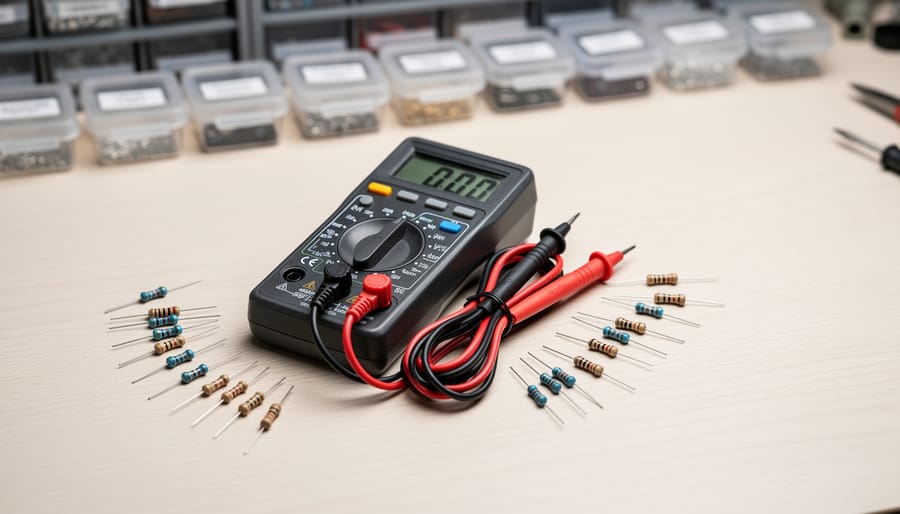
- Digital multimeter or ohmmeter for measuring actual resistance values
- Complete circuit schematic showing all resistor connections and configurations
- Resistor specifications including nominal values, tolerance percentages, and power ratings
- Paper and pencil or circuit drawing software for sketching simplified networks
- Access to the Series-Parallel Resistor Calculator for verification and complex networks
Your circuit diagram doesn’t need to be perfect, but it must show which resistors connect in series (end-to-end) and which share common nodes in parallel. If you’re working with an existing circuit, photograph or sketch it clearly before disconnecting anything. For solar applications like bypass diode circuits or current-sensing networks, identify each component’s position in the overall system.
Having resistor tolerances matters more than many realize. A 10% tolerance on a 100Ω resistor means the actual value could range from 90Ω to 110Ω. When multiple resistors combine in series-parallel arrangements, these tolerances compound. Document them now rather than wondering later why your measured total resistance differs from calculated values.
The calculator tool handles complex networks instantly, but you should understand the manual process first. That foundation lets you spot input errors, verify unusual results, and troubleshoot when measured values don’t match predictions. Keep both your measurement tools and the calculator accessible throughout the process.
Understanding Series-Parallel Resistor Networks
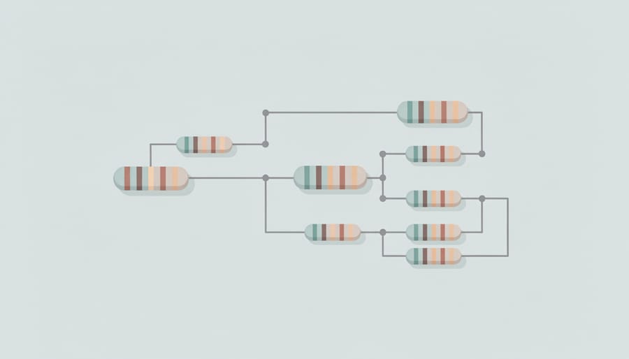
Series and parallel resistor configurations represent two fundamental ways resistors combine in electrical circuits. Understanding each type separately forms the foundation for analyzing more complex mixed networks.
Series Configuration
Resistors connected in series form a single path for current flow, with each resistor encountered one after another. In this arrangement, the same current flows through all resistors, but the voltage divides across them. The total resistance equals the sum of individual resistances:
R_total = R1 + R2 + R3 + …
This straightforward addition makes series calculations simple. For example, three resistors of 100Ω, 220Ω, and 330Ω in series produce 650Ω total resistance.
Parallel Configuration
Parallel resistors connect to the same two points, creating multiple paths for current. Here, voltage remains constant across all resistors while current divides among them. The formula uses reciprocals:
1/R_total = 1/R1 + 1/R2 + 1/R3 + …
For two resistors only, the product-over-sum shortcut works: R_total = (R1 × R2)/(R1 + R2). Parallel combinations always produce lower resistance than the smallest individual resistor.
Why Mixed Networks Need Systematic Analysis
Real-world circuits rarely contain purely series or purely parallel arrangements. Solar panel bypass systems, battery monitoring circuits, and LED arrays typically combine both configurations. These mixed networks can’t be solved with a single formula application. Instead, you must identify distinct series and parallel groups, calculate their equivalent resistances step by step, and progressively simplify the circuit until reaching a single value. Without this methodical approach, errors multiply quickly, especially in networks containing five or more resistors.
Critical Warnings and Common Mistakes
Never work with live circuits when measuring resistance values. Always disconnect power sources completely and discharge any capacitors before taking measurements, applying a multimeter to an energized circuit can damage the meter, destroy components, or create a shock hazard. In solar installations, this means disconnecting panels from inverters and charge controllers, even on cloudy days when voltage may seem negligible.
The most frequent calculation error occurs when students misidentify circuit topology. A resistor that appears parallel in a schematic might actually be in series depending on current path, trace the electron flow carefully rather than relying on visual layout alone. In complex networks, sketch simplified intermediate steps to avoid losing track of which groups you’ve already combined.
Power dissipation represents another critical concern, especially in solar charge controllers and battery management circuits. A correctly calculated resistance value means nothing if the physical resistor can’t handle the wattage. Calculate power using P = I²R or P = V²/R for each component, then select resistors rated at least 50% above calculated dissipation for reliability. Standard quarter-watt resistors fail quickly in solar applications where continuous current flows for hours.
Tolerance stack-up becomes significant in voltage dividers and current sensing applications. When multiple resistors combine, their individual tolerances compound, potentially shifting your final equivalent resistance by 10% or more. For precision work, use 1% metal film resistors and measure actual values before installation.
Step-by-Step Calculation Process
Step 1: Draw and Label Your Circuit
Start by creating a clear visual representation of your circuit on paper or using circuit drawing software. Draw each resistor as a zigzag symbol or rectangle, maintaining consistent spacing between components. Label every resistor with both a reference designator (R1, R2, R3) and its resistance value in ohms.
Mark the current path through the circuit with arrows to identify how electricity flows. This reveals which resistors share the same current (series) and which share the same voltage (parallel). Use colored pencils or highlighters to group resistors that connect end-to-end without branches, these form your series groups. Circle resistors that share both connection points, indicating parallel arrangements.
For complicated schematics with crossing wires and unclear connections, redraw the circuit. Straighten the current path into a simple left-to-right layout. Remove unnecessary wire bends and position parallel branches directly above or below each other. This clean diagram becomes your working reference for the remaining calculation steps, preventing confusion when you simplify groups later.
Step 2: Identify Series Groups
Resistors are in series when current flows through them sequentially with no alternate paths, picture beads on a single string. The key characteristic: they share identical current flow because electrons have only one route.
To identify series groups, trace the current path from one connection point through each resistor to the next. If no wire branches off between two resistors, they’re in series. Look for these telltale signs: components connected end-to-end, no junction splitting the current, and the same wire connecting consecutive resistors without interruption.
Once identified, calculating series resistance is straightforward, just add the individual values:
R_total = R1 + R2 + R3 + …
In solar panel bypass circuits, three 0.5-ohm resistors often connect in series to create voltage drops for monitoring purposes. The total resistance becomes simply 1.5 ohms (0.5 + 0.5 + 0.5). This additive property makes series configurations predictable and easy to analyze first before tackling more complex parallel sections of your network.
Mark these grouped resistors on your diagram with brackets or highlight them, you’ll replace them with their equivalent value in Step 4.
Step 3: Identify Parallel Groups
Once you’ve simplified series groups, look for resistors that share the same two connection points, these are in parallel. Trace the circuit carefully: parallel resistors will have their terminals connected to the exact same nodes, creating multiple paths for current flow. Mark these groups with brackets or circles on your diagram.
For parallel resistors, the total resistance is always lower than the smallest individual resistor in the group. Calculate using the reciprocal formula:
1/R_total = 1/R₁ + 1/R₂ + 1/R₃…
For just two resistors, the product-over-sum shortcut is faster: R_total = (R₁ × R₂) ÷ (R₁ + R₂).
In solar charge controllers, current sensing circuits often use parallel resistor networks to achieve precise low-resistance values. A typical design might place a 0.01Ω resistor in parallel with a 0.02Ω resistor across the current path. Using the shortcut: (0.01 × 0.02) ÷ (0.01 + 0.02) = 0.00667Ω. This combined resistance creates a measurable voltage drop proportional to current without excessive power loss.
Remember: parallel resistors reduce total resistance, while series resistors increase it. Double-check your node connections before applying the formula.
Step 4: Simplify the Network Progressively
Start with the simplest combination you identified, either a series group or a parallel group, and replace it with its equivalent resistance. Redraw the circuit with this single resistor in place of the group, keeping all other components in their original positions.
Label this new equivalent resistor clearly with its calculated value, then examine the redrawn circuit for the next simplest combination. You’ll often find that simplifying one group reveals new series or parallel relationships that weren’t obvious in the original schematic.
Continue this process iteratively: calculate, replace, redraw, and identify the next group. In a typical solar charge controller current-sensing network, you might reduce six resistors to three, then to two, and finally to one total equivalent resistance.
Keep each intermediate drawing, these show your work and help troubleshoot if your final answer seems incorrect. The process always ends with exactly one resistor value representing the entire network’s resistance between the two points of interest.
Step 5: Use the Calculator to Verify
After completing your manual calculations, open the Series-Parallel Resistor Calculator to verify your work. Enter each resistor value in the appropriate field, selecting whether components connect in series or parallel using the dropdown menu. The calculator processes your inputs instantly and displays the equivalent resistance.
Compare the calculator’s output with your hand-calculated result. They should match within 1-2% accounting for rounding differences. If there’s a significant discrepancy, review your simplification steps, you likely miscategorized a group or made an arithmetic error.
The calculator also shows intermediate calculations when you expand the detailed view. This feature helps you pinpoint exactly where a manual calculation went wrong. For complex networks with multiple parallel branches, the calculator eliminates tedious reciprocal arithmetic while you focus on correctly identifying the circuit topology.
Use the calculator’s save feature to document your verified results for project records. For circuits with ten or more resistors, the calculator becomes essential, manual calculation error rates climb sharply beyond that complexity threshold.
Verifying Your Results
Once you’ve calculated the total resistance of your series-parallel network, verification prevents costly errors in your solar installation or electronics project. The simplest check is physical measurement with a digital multimeter set to the resistance (Ω) range. Disconnect the resistor network from any power source and place the meter probes across the input and output terminals. The reading should match your calculated value within the component tolerance range.
For additional confidence, recalculate using a different simplification order. If you simplified left-to-right initially, work right-to-left or tackle parallel groups first instead of series groups. The final equivalent resistance must be identical regardless of which valid path you choose through the network.
Resistor tolerances matter significantly. Standard resistors carry ±5% or ±10% tolerance bands, meaning a 100Ω resistor could legitimately measure between 95Ω and 105Ω (5% tolerance) or 90Ω to 110Ω (10% tolerance). When multiple resistors combine, these variations compound. A measured value within 8-12% of your calculated result typically indicates correct methodology with normal component variation.
When measurements don’t match calculations, first verify you’ve correctly identified the series and parallel groupings in your circuit diagram. Check for hidden connections, ensure no resistors are bridged by solder joints or wire fragments, and confirm each resistor value matches your diagram. Temperature can shift resistance values slightly, particularly in high-power solar applications. If discrepancies persist beyond tolerance ranges after checking these factors, consult the circuit designer or re-evaluate your network analysis from the beginning.
Real-World Applications in Solar and Electronics
Series-parallel resistor networks appear throughout solar installations and electronic systems, and accurate calculation directly impacts reliability and efficiency. In photovoltaic arrays, bypass diodes work with series-connected resistors to protect panels from hot-spot damage during partial shading. Miscalculating these networks can lead to inadequate current limiting, potentially destroying expensive solar cells.
Battery management systems rely heavily on mixed resistor networks for voltage sensing and current measurement. Voltage dividers using series-parallel configurations step down battery pack voltages to safe levels for monitoring circuits. When designing these dividers, engineers must calculate battery EMF accurately and ensure the divider network matches the measurement range. Incorrect resistance values cause false readings that trigger unnecessary shutdowns or fail to detect dangerous overcharge conditions.
LED arrays in solar-powered lighting use current-limiting resistors in series-parallel arrangements to balance brightness across multiple strings. Each string typically contains 3-10 LEDs in series with a limiting resistor, and multiple strings run in parallel. Getting these calculations wrong results in uneven illumination or premature LED failure from overcurrent.
Charge controllers employ series-parallel networks in their current-sensing circuits. A shunt resistor measures current flow, often requiring engineers to convert amps to mA when working with low-power applications. The sensing circuit combines this shunt with filtering resistors in mixed configurations. Calculation errors here translate to inaccurate charging algorithms that undercharge or overcharge batteries, reducing system lifespan.
Frequently Asked Questions

What’s the difference between series and parallel resistors?
Series resistors connect end-to-end in a single path where the same current flows through each one, and you add their values directly. Parallel resistors share the same two connection points where current splits between them, requiring the reciprocal formula to calculate equivalent resistance.
Which groups should I calculate first in a mixed network?
Start with the innermost or most obvious groups, whether series or parallel. The order doesn’t affect the final result as long as you simplify systematically, replacing each calculated group with its equivalent resistance before moving to the next.
How do I handle more than two resistors in parallel?
Use the reciprocal formula: 1/R_total = 1/R1 + 1/R2 + 1/R3 + … For three 100Ω resistors in parallel, that’s 1/R_total = 1/100 + 1/100 + 1/100 = 3/100, so R_total = 33.3Ω. The calculator handles any number of parallel resistors automatically.
Why do my measured values differ from calculated ones?
Resistor tolerance (typically 5% or 10%) means actual values vary from their nominal rating. Temperature, solder joint resistance, and meter accuracy also introduce small differences. A variance within the stated tolerance is normal and acceptable for most applications.
When working with precision applications like charge controller sensing circuits or battery management systems, standard tolerance resistors may not suffice. Precision resistors (1% or 0.1% tolerance) cost more but ensure your built circuit matches calculated behavior. For solar energy calculations beyond resistor networks, you might also need to convert between units, for instance, using Ah to Wh when sizing battery banks or kWh to Ah when matching panel output to storage capacity.
Manual calculations teach you the underlying principles and help you catch errors, but for networks with six or more resistors, software tools save time and reduce arithmetic mistakes. Use manual methods to verify your understanding, then rely on the calculator for production work where speed and accuracy both matter.
Mastering series-parallel resistor calculations requires practice with real-world circuits, not just theory. The five-step process, drawing, identifying series groups, spotting parallel arrangements, simplifying systematically, and verifying with the calculator, provides a reliable framework for even the most complex networks. Start with simple two-resistor combinations, then tackle circuits with three to four elements before moving to elaborate solar charge controller or battery management layouts.
The Series-Parallel Resistor Calculator serves as both a learning tool and professional verification resource. Use it to check your manual work initially, then reverse the process: input known equivalent resistances and work backward to understand how different configurations achieve specific values. This bidirectional practice strengthens your circuit analysis intuition.
For solar and electronics professionals, accurate resistor network calculation directly impacts system efficiency, component longevity, and installation safety. Make these calculations routine practice, and you’ll develop the confidence to troubleshoot and optimize designs rapidly in the field.